4.0-TX-8CH-DF-WG-DT Anti-jam
The 3.0pro-GNSS-12V anti-jamming module offers enhanced GNSS security for UAVs and unmanned vehicles. With advanced anti-interference features, it supports reliable satellite signal reception even in challenging environments, making it ideal for critical navigation and timing applications in logistics, defense, and infrastructure.
Description
Product Presentation
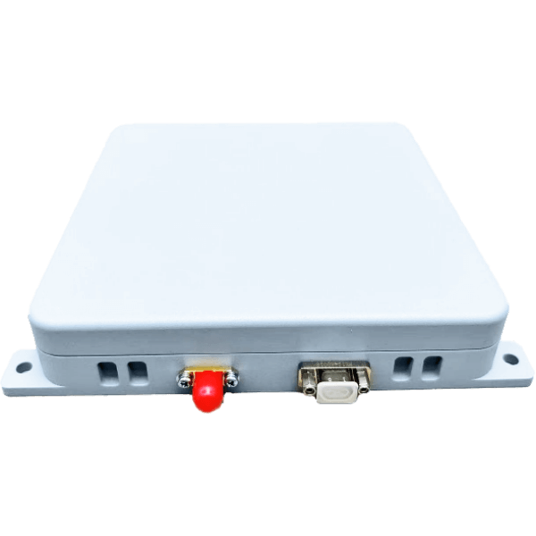
This product, model 4.0-TX-4CH-DF-WG-DT, is a miniaturized satellite navigation anti-jamming integrated machine designed for civil unmanned aerial vehicles and industry user needs. It supports the reception of Beidou-3 RNSS B1/B3 dual-frequency signals and has the capability to resist broadband jamming on both B1/B3 frequencies, with a maximum resistance to 3 interference sources. It integrates an internal antenna array, anti-jamming components, and a satellite navigation receiver, serving fields such as reliable navigation for drones and unmanned vehicles, protecting user terminals from various unintentional interference and malicious attacks, and greatly enhancing the security of PNT information.
Product Features
- RNSS signal reception
- It has the function of receiving RNSS signals from Beidou 2 and Beidou 3 navigation satellites.
- Civil code: B1C, B1I, B3I
- Anti-interference capabilityWith the anti-interference function of B3 and B1 frequency points, it can suppress narrowband interference, broadband interference, pulse interference, sweep interference, Gaussian interference, and other suppression interference.
- Software upgradeWith the software upgrade function, you can upgrade the anti-interference module and the receiver module through the serial port.
- System self-inspectionIt has self-check and status inspection functions.
- Interference detectionWith the interference detection function, it can identify the interference power.
- Anti-burnout functionContinuous wave power resistance not less than 10W.
- SecurityWith overvoltage protection, reverse connection protection, reverse conduction protection, etc.
Electrical Performance
- Operating frequency
- B3: 1268.52MHz ± 10.23MHz
- B1: 1575.42MHz ± 16.368MHz
- Anti-interference performanceSingle interference dry letter ratio: 95dB, three interference dry letter ratio: 85dB
- Positioning accuracyLevel of 10 m (95%), elevation of 10 m (95%)
- Rate accuracy0.2 m/second (95%)
- Timing accuracy≤100ns (95%)
- Operating voltageThe input voltage is 5 to 17 V
- Power consumption≤17W
Note: For B3 or B1 single-frequency point anti-interference, the power consumption is 10W.
Interface Definition
Power/Data Interface
The J30J-9 ZK core connector is selected, and the pin is defined as follows:
| Pipe Foot Number | Pipe Foot Name | Direction | Electrical Level | Remarks |
|---|---|---|---|---|
| 1 | Power input positive pole | Power input | 5~17V | |
| 2 | Power input positive pole | Power input | 5~17V | |
| 3 | Power input negative electrode | Power input | ||
| 4 | Power input negative | Power |
| Electrode | Input | Electrical Level | Remarks |
|---|---|---|---|
| TXD0 | Output | TTL | Receiver |
| RXD0 | Import | TTL | String port |
| RXD1 | Output | TTL | Anti-interference string mouth |
| TXD1 | Output | TTL | |
| GND | Import | TTL |
RF Interface
- Anti-interference signal output interface (reserved), using SMA connector, and for the first-line form.
- The signal level of the output B3 \ B1 is -70 ~ -60 dBm.
Structural Requirements
- Dimension150mm × 130mm × 26.5mm
- Weight≤500g (TBD)
- ColorFrench grey
Product Identification
| Product name: | |
| Product model: | |
| Serial number: | |
| Production date: | |
| Manufacturer: |
Environmental Adaptability
- Operating temperature: -40°C to +55°C
- Storage temperature: -55°C to +70°C
- Relative humidity: At 40°C temperature; 96% humidity
- Rain resistance: Meets the requirements of GJB150A rain test
Typical Application Occasions
- Timing safety in power, communication, finance, and other fields
- Navigation safety of unmanned aerial vehicles, unmanned vehicles, and unmanned ships
- Fleet defense and navigation security
- High-end logistics navigation security
Connection Description
The electrical signal connection of the product and the platform carrier is connected by low-frequency data mode. This product replaces the conventional positioning terminal.
In the RF signal access mode, this product replaces the conventional active antenna.
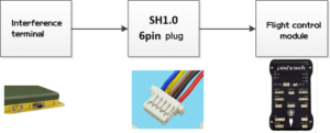
Note: When using a USB to TTL tool to connect to the computer, do not plug USB to avoid damage to the serial port.
Example of Positioning Module Protocol Configuration
PIXHAWK Open Source Flight Control
Step 1: Configure the positioning module. Through the TTL to USB conversion line connected to the personal computer, use the serial port debugging assistant software to send configuration instructions, and save. You must check “return line” when sending instructions.
| Instruct | Meaning |
|---|---|
| unlogall | Stop all protocol output |
| log gngga ontime 0.2 | The 0.2-s interval outputs the GGA, and the minimum interval can be configured as 0.1 |
| log gnrmc ontime 0.2 | The RMC was output at the 0.2-s interval |
| log g p vtg ontime 0.2 | The VTG was output at a 0.2-s interval |
| log pgrmv ontime 0.2 | The RMV was output at the 0.2-s interval |
| log gp gsv ontime 0.2 | GSV at 0.2s interval |
| SAVECONFIG | Maintain the configuration and send the data following the above instructions |
| Instruct | Meaning |
|---|---|
| unlogall | Stop all the output |
| log gngga ontime 0.2 | 0.2s interval output GGA |
| log gnrmc ontime 0.2 | 0.2s interval output RMC |
| log gpvtg ontime 0.2 | 0.2s interval output VTG |
| log pgrmv ontime 0.2 | 0.2s interval output RMV |
| log gpgsv ontime 0.2 | 0.2s interval output GSV |
| SAVECONFIG | Save the configuration to the flash |
The above instructions only need to be configured once, and the subsequent boot-up automatically sends the data according to the above instructions.
The second step is to connect the 3-foot DuPont line: white line TX to the RX of flight control, red line RX to the TX of flight control, and black GND to the GND of flight control.
Beijing Chuangheng Flying Control
Step 1: Configure the positioning module. Through the TTL to USB conversion line connected to the PC, use the serial interface debugging assistant to send configuration instructions, and save.
| Instruct | Meaning |
|---|---|
| unlogall | Stop all protocol output |
| LOG COM1 BESTPOSB ONTIME 0.2 | Output position information at the 0.2-s interval |
| LOG COM1 BEST VEL B ONTIME 0.2 | Output speed information at 0.2s interval |
| LOG COM1 PSRDOPB ONTIME 0.2 | The 0.2-s interval of the output accuracy information |
| SAVECONFIG | Maintain the configuration and send the data following the above instructions |
Usage Summary
In general, this product is relatively simple to use. The following main steps:
- Fixed. Install fixation with M3 screws.
- Power supply. Use XT30, supply voltage 5-17V, maximum 17V.
- Position the data connection. Connect the DuPont line TTL serial port of this product to the flight control GNSS serial port.
Description of Data Protocol
Using the NEMA 0183 protocol format, the current output protocols are mainly as follows:
| Fixed Position | GGA |
|---|---|
| Satellite | GSV |
| Minimum Location Information | RMC |
Identification of the Four Major Satellite Navigation Systems
| GP | GPS System |
|---|---|
| GB | Beidou System |
| GL | GLONASS System |
| GA | GALILEO System |
| GN | GNSS Mixing |
GPGGA Example
GPGGA, 092204.999, 4250.5589, S, 14718.5084, E, 1, 04, 24.4, 19.7, M, 0000 * 1F
- Field 0: GPGGA – Statement ID, indicating that the statement is the Global Positioning System Fix Data (GGA) GPS location information.
- Field 1: UTC time, hhmmss.sss format (hour-minute-second).
- Field 2: Latitude ddmm.mmmm, Degree format (if leading number is insufficient, fill with 0).
- Field 3: Latitude N (North) or S (South).
- Field 4: Longitude ddmm.mmmm, Degree format (if leading number is insufficient, fill with 0).
- Field 5: Longitude E (East) or W (West).
- Field 6: GPS status, 0 = un, 1 = non-differential, 2 = differential, 3 = invalid PPS, 6 = under estimation.
- Field 7: Number of satellites in use (00-12) (fill with 0 if insufficient).
- Field 8: HDOP Level Precision Factor (0.5-99.9).
- Field 9: Altitude (-9999.9 to 99999.9).
- Field 10: Height of the earth ellipsoid relative to the geoid.
- Field 11: Differential time (seconds from last differential signal received, empty if not differential location).
- Field 12: Differential station ID # 0000-1023 (insufficient lead 0, empty if not differential).
- Field 13: Check value.
GPGSV Example
GPGSV,3,1,10,20,78,331,45,01,59,235,47,22,41,069,13,32,252,45 * 70
- Field 0: GPGSV – Statement ID, indicating that the statement is GPS Satellites in View (GSV) visible satellite information.
- Field 1: Total number of current GSV statements (1-3).
- Field 2: This GSV statement is the first clause (1-3) of this GSV statement.
- Field 3: Total number of current visible satellites (00-12) (fill 0 if insufficient).
- Field 4: PRN code (pseudo-random noise code) (01-32) (fill 0 if insufficient).
- Field 5: Satellite elevation (00-90) (fill 0 if insufficient).
- Field 6: Satellite azimuth (00-359) (fill 0 if insufficient).
- Field 7: Signal to noise ratio (00-99) dBHz.
- Field 8: PRN code (pseudo-random noise code) (01-32) (fill 0 if insufficient).
- Field 9: Satellite elevation (00-90) (fill 0 if insufficient).
- Field 10: Satellite azimuth (00-359) (fill 0 if insufficient).
- Field 11: Signal to noise ratio (00-99) dBHz.
- Field 12: PRN code (pseudo-random noise code) (01-32) (fill 0 if leading digit is insufficient).
- Field 13: Satellite elevation (00-90) (fill 0 if insufficient).
- Field 14: Satellite azimuth (00-359) (fill 0 if insufficient).
- Field 15: Signal to noise ratio (00-99) dBHz.
- Field 16: Check value.
GPRMC Example
GPRMC, 024813.640, A, 3158.4608, N, 11848.3737, E, 10.05, 324.27, 150706, A * 50
- Field 0: GPRMC – Statement ID, indicating that the statement is Recommended Minimum Specific GPS/TRANSIT Data (RMC) recommended minimum location information.
- Field 1: UTC time, hhmmss.sss format.
- Field 2: Status, A = positioned, V = unpositioned.
- Field 3: Latitude ddmm.mmmm, Degree format (fill with 0 if leading number is insufficient).
- Field 4: Latitude N (North) or S (South).
- Field 5: Longitude ddmm.mmmm, Degree format (fill with 0 if leading number is insufficient).
- Field 6: Longitude E (East) or W (West).
- Field 7: Speed, section, Knots.
- Field 8: Azimuth, degree.
- Field 9: UTC date, in DDMMYY format.
- Field 10: Magnetic bias angle, (000-180) (fill 0 if insufficient).
- Field 11: Magnetic angle, E = East, W = West.
- Field 16: Check value.
GNJAM Example
GNJAM, 23.1,23.1,23.1,23.1,32,32,32,32,0,*68
- Field 1: Channel 1 power.
- Field 2: Channel 2 power.
- Field 3: Channel 3 power.
- Field 4: Channel 4 power.
- Field 5-8: Debug information.
- Field 9: Spectrum identification.
- Field 10: End of the data frame.
Directive Preparation
- Use the TTL to USB transfer cable to connect the TTL output port of the anti-interference terminal with the personal computer.RX of the white TX adapter, TX of the red RX adapter, GND of the black GND adapter.
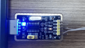
- Run sscom.exe, select the communication port corresponding to the above transfer cable, configured with a port rate of 115200.
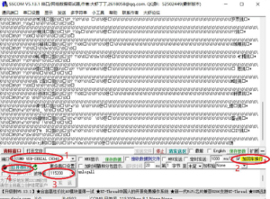
Note: After entering unlogall, please return.
- Confirm the hardware connectivity.Use ASCII characters to send “unlogall” and check the return line to send.

The return data in the fourth step can be seen, indicating that the hardware is connected and the terminal responds to the instructions sent normally.
Instruction Set
Send the following instructions successively. After each instruction is sent, it will return “response: OK,” indicating that the instruction responds normally.
| Instruction | Meaning |
|---|---|
| unlogall | Stop all the output |
| log gngga ontime 0.2 | 0.2s interval output GGA |
| log gnrmc ontime 0.2 | 0.2s interval output RMC |
| log gpvtg ontime 0.2 | 0.2s interval output VTG |
| log pgrmv ontime 0.2 | 0.2s interval output RMV |
| log gpgsv ontime 0.2 | 0.2s interval output GSV |
| SAVECONFIG | Save the configuration to the flash |
0.2 in the instruction indicates the 0.2s interval. It can be configured as required. Maximum support is 10Hz, or an interval of 0.1s.
The above instructions only need to be configured once, and the subsequent boot-up automatically sends the data according to the above instructions. These instructions are for when the anti-jamming terminal is connected with the open-source Pixhawk flight control. When docking with other types of flight control, the configuration needs to be adjusted according to the data requirements of the specific flight control.
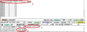
- Turn off the power, connect the TTL of the positioning data to the Pixhawk, and observe the GPS work display in the flight control interface after the restart. It should be noted that the anti-interference terminal needs to be placed in an area that can normally receive satellite signals.
Disclaimer
This product is designed to improve the security of satellite navigation. Please comply with relevant laws and regulations during use. Any illegal activities using the product are prohibited.
Reviews
There are no reviews yet.